
The package used in the production in many of these models in NEC2 which is great at detail but not so good at graphical output hence all of the plots are produced by hand from the original data.
Models are sorted by the 'owner' of the aerial concerned - remember they are models and antennas have a habit of behaving just as they please depending upon local conditions despite the theory !
G0DUB
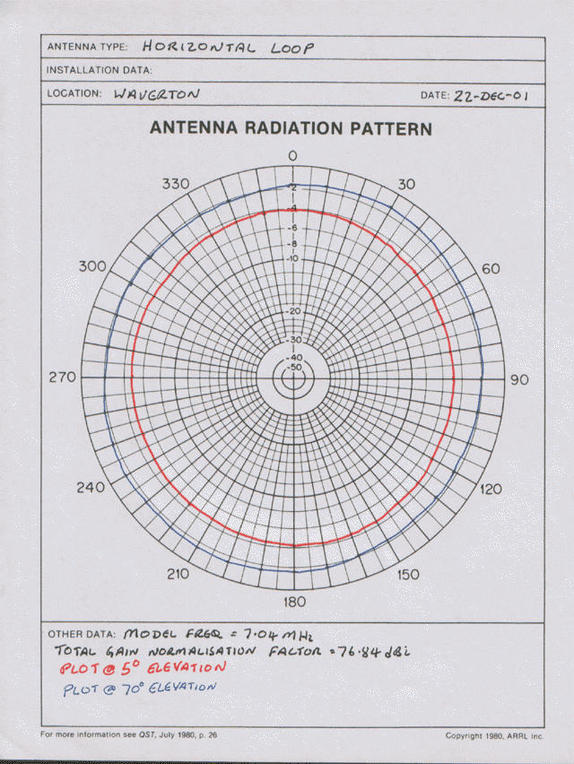
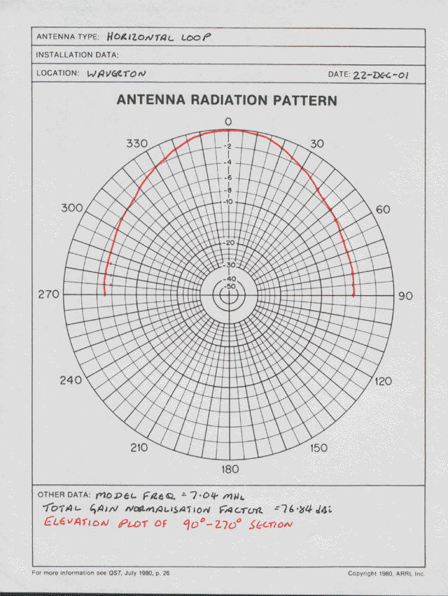
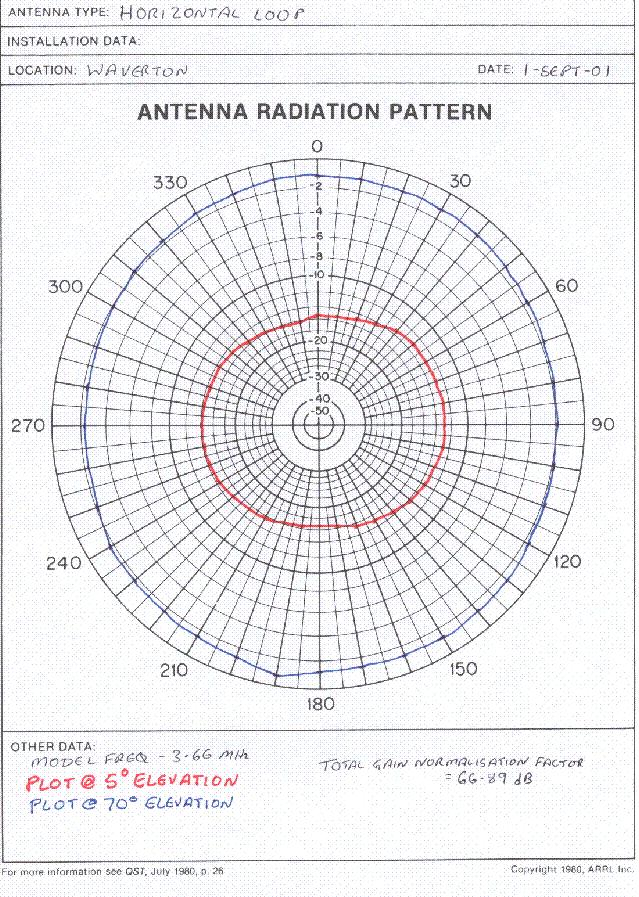
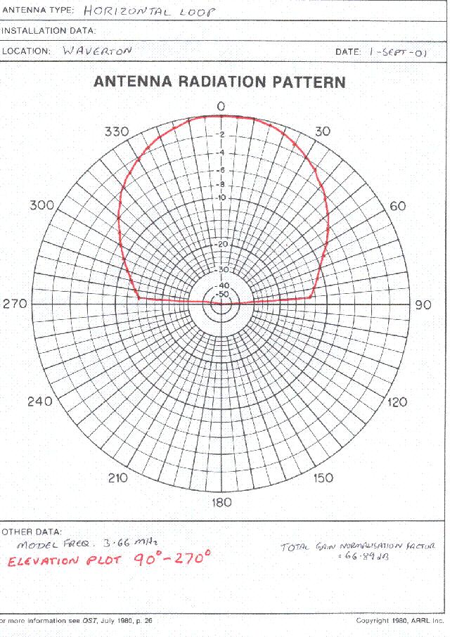
200ft horizontal loop - this was from the 'maximum wire - maximum enclosed area' school of thought. The antenna had around 200 ft of stranded wire draped over the roof of my bungalow then supported by 10ft bamboo canes in the back garden to make up the rest of the loop. It worked well but not as well as the model predicted, eventually this antennas downfall was the poor performance on the HF bands, I only have room for one or two antennas and full HF coverage is required.
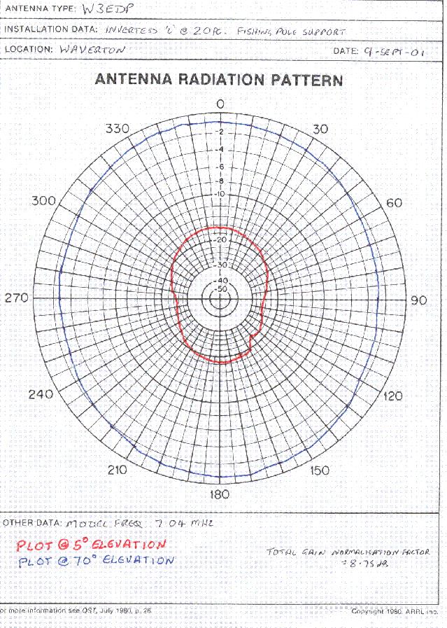
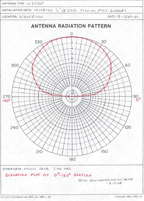
W3EDP - the workhorse of many stations, an 85ft wire driven against a 17ft counterpoise. Originally designed for use on 80 through to 10m ( excluding the WARC bands ) the antenna is an end fed wire with the counterpoise acting as a length of transmission line on some bands to make the impedance a little easier to match. It was modelled as an inverted-L 20ft off the ground which is the normal way I deploy this antenna in the field.
- Loop performance on 7MHz - azimuth plot and elevation plot
- Loop performance on 3.663MHz - azimuth plot and elevation plot
- Raw NEC2 output for 3.5 Mhz in .zip format
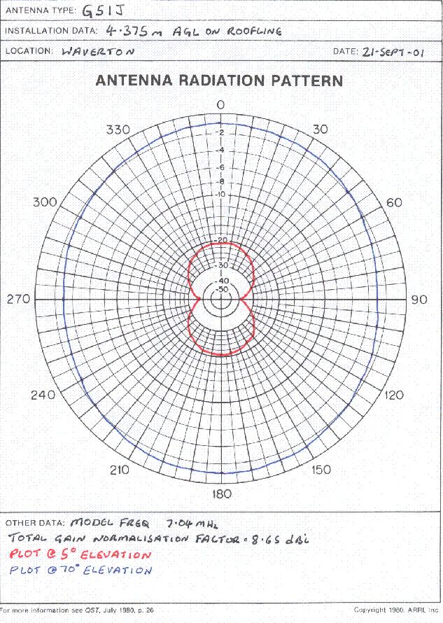
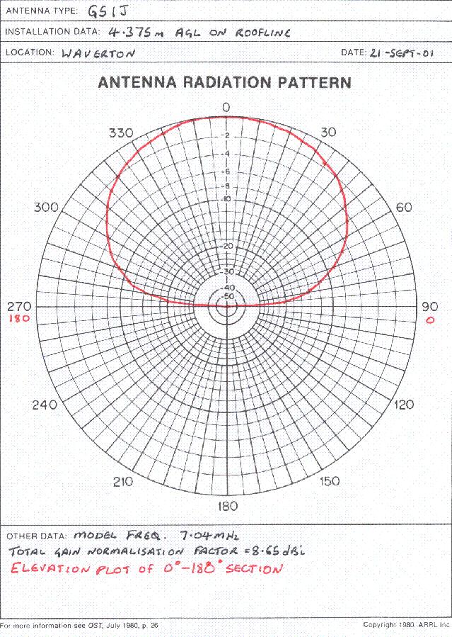
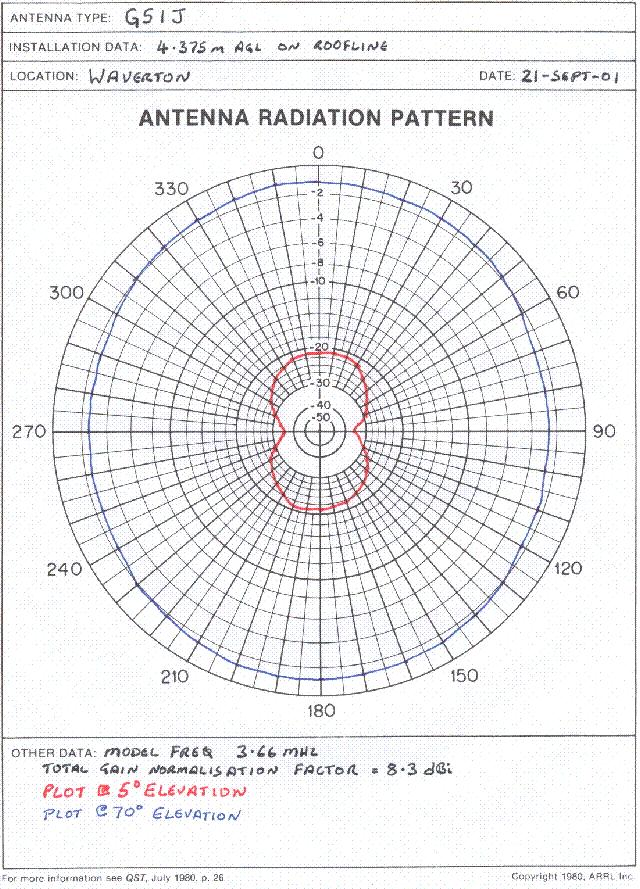
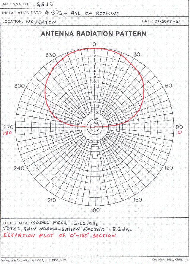
G5IJ - Another end-fed wire. This one was run along the apex of the bungalow roof at 14ft agl. A transformer takes a co-ax feed and drives the end fed wire directly. A more detailed technical description will follow shortly.
- W3EDP performance on 7MHz - azimuth plot and elevation plot
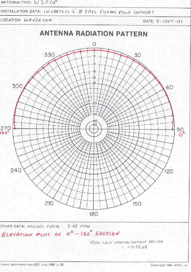
- W3EDP elevation plot on 3.663MHz - the pattern is so flat on 80m it wasn't worth plotting the azimuth pattern !
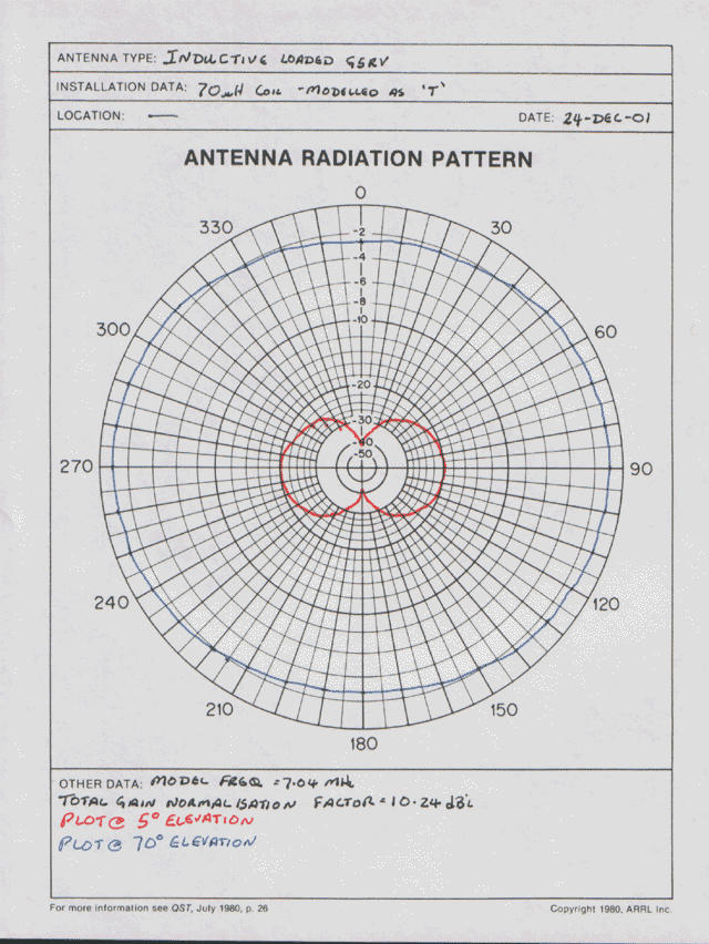
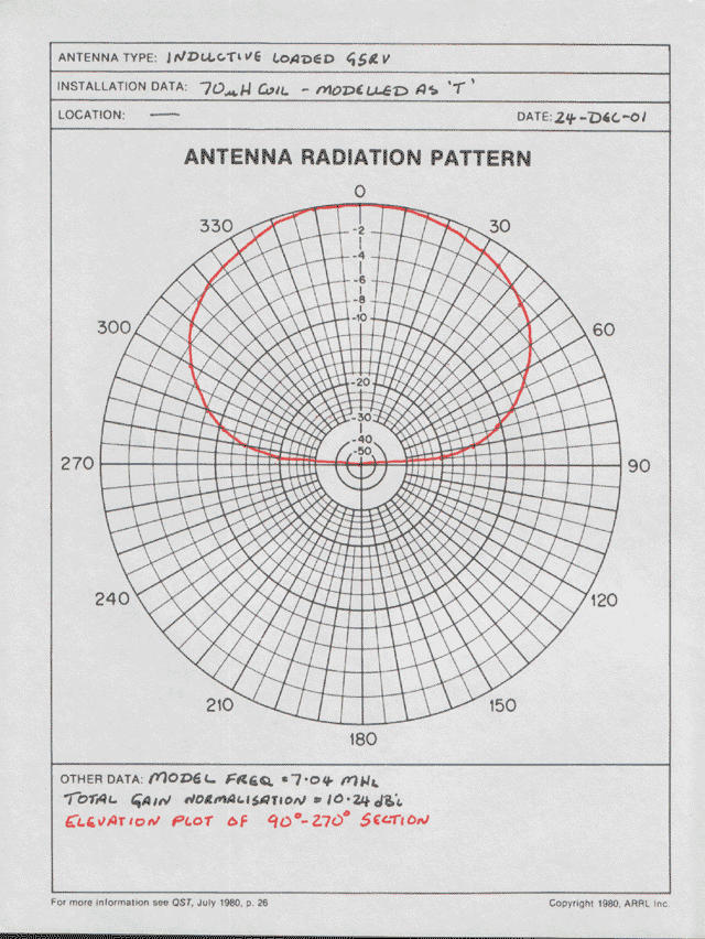
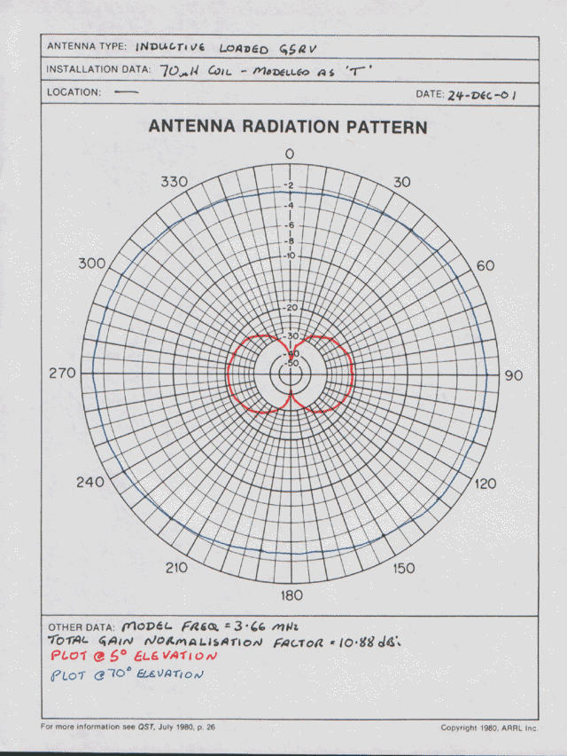
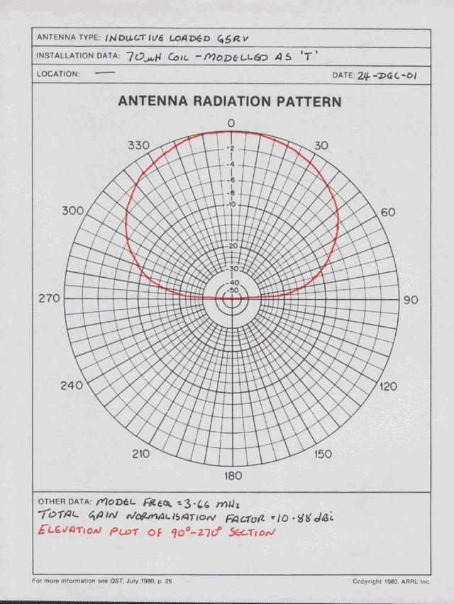
Half sized G5RV extended to 80m with loading coils - Antenna is a standard 51ft half sized G5RV with the addition of loading coils and 8ft of wire on each end to extend coverage to 80m. The antenna was supported off the TV pole at the end of the bungalow so the apex of the antenna was about 14ft off the ground one element lying on the roof and the other in free space decending to about 8ft agl at the bottom of the garden. For ease this was modelled as if it was in a flat-T formation which will distort the results.
- G5IJ performance on 7MHz - azimuth plot and elevation plot
- G5IJ performance on 3.663MHz - azimuth plot and elevation plot
- Inductively loaded G5RV performance on 7MHz - azimuth plot and elevation plot
- Inductively loaded G5RV performance on 3.663MHz - azimuth plot and elevation plot
G4HPE
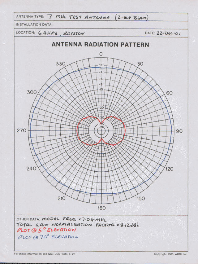
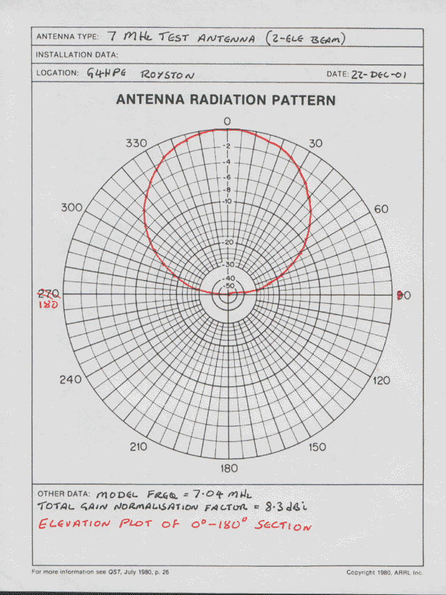
2-element vertical beam - this antenna is best described by this picture . Almost an NVIS classic, the low dipole already has a high angle of elevation which is reinforced by the reflecting element beneath.M5WJF
- Antenna performance on 7MHz - azimuth plot and elevation plot
- Raw NEC2 output file for 7MHz in plain text format ( .out )
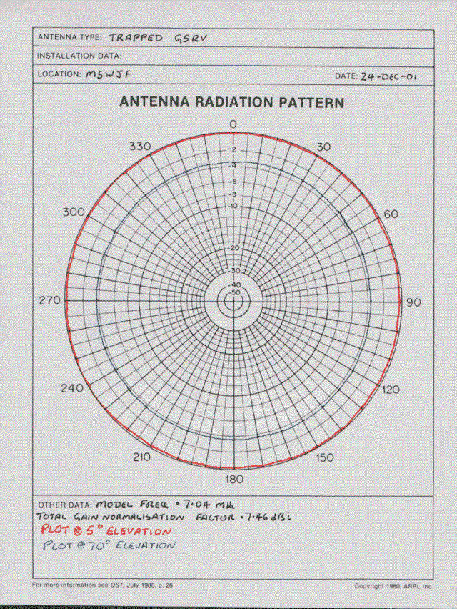
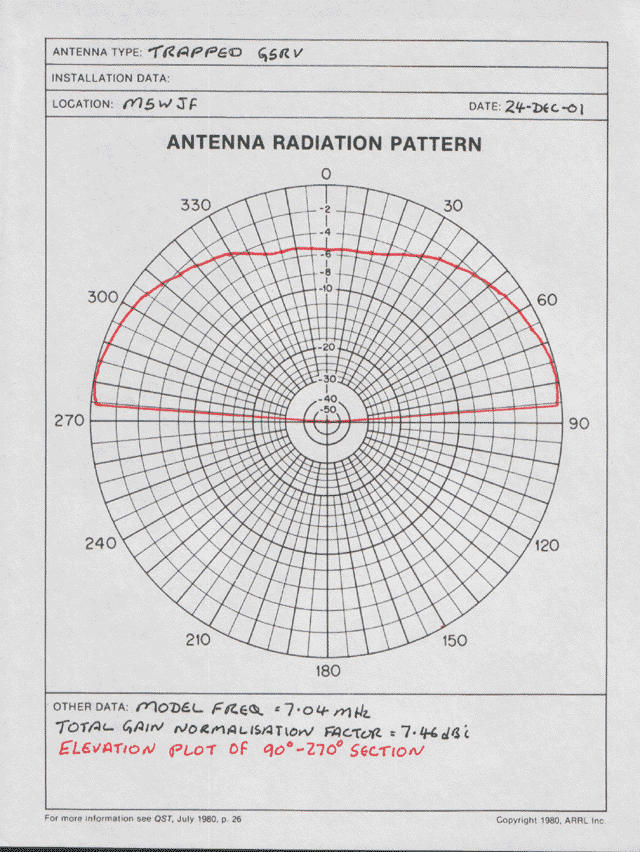
Half sized G5RV extended to 80m with traps - Antenna is standard 51ft half-wave G5RV, with 40m traps and tails added to extend the overall length to 68ft. One end connected to a 9ft scaffold pole mounted on a 24 inch T & K assembly on the side of my house, with the insulator fixed at approximately 20ft AGL. The other end is at the top of the garden connected to the top of a 20ft scaffold pole mounted 4ft into the ground, the run is slightly too short for the antenna, so another insulator is employed together with cable ties (threading the G5RV to allow movement of the antenna), allowing an ~11ft section (which includes a 40m trap) being led down backwards, but angled at around 45 degrees towards a cleat fixed to the corner fence post at the top of the garden (needs must).
- Antenna performance on 7MHz - azimuth plot and elevation plot
- Antenna performance on 3.663 MHz - azimuth plot and elevation plot
- Raw NEC2 output file for 7MHz in plain text format ( .out )
- Raw NEC2 output file for 3.663 MHz in plain text format (.out)
Click here to return
to the RAYNET HF Team mainpage
Page updated by Greg Mossop G0DUB 23/05/02. Header Graphic
by Paul Gaskell (c) 7/5/01